The mechanical approach of
the sample to the tip.
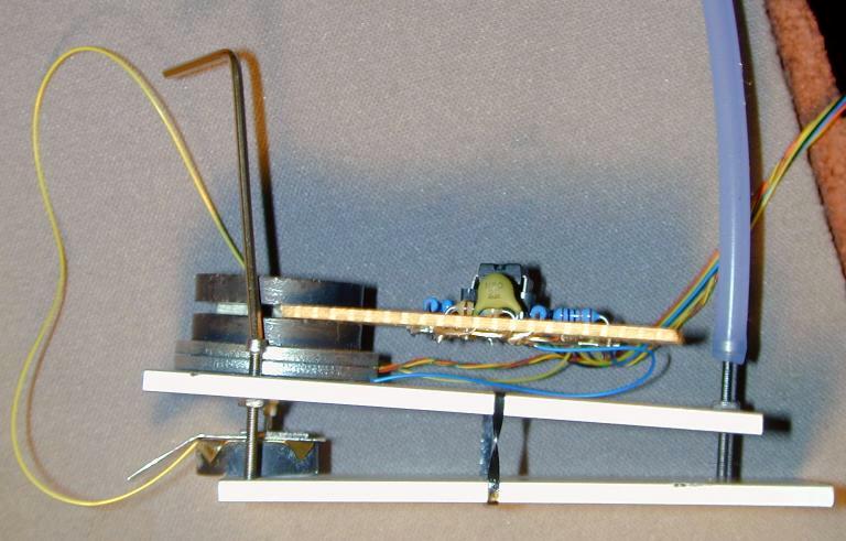
The coarse approach is made with a lever (sample stage) moved by three fine thread machine screws.
I used three UNCF #1-72 screws so at 72 threads per inch that comes to 353
microns (0.353 mm) per turn of the screw. The Z servo range of this unimorph
is only about 3 microns (0.003 mm). The coarse motion of the sample relative
to the tip must be controlled within this 3-micron range to stop the tip
from crashing into the sample. There are two screws on a line about 1 mm
in front of the STM tip. These screws provide a very coarse approach. Because
the tip is about half way between them the Z motion of the sample from these
screws is about 176 microns per turn. The third screw is about 70-mm away
form the line of the first two screws (fulcrum). The Z motion of the tip
is 1/70 of 353 or 5.04 microns per turn. There is only a range of about a
half a turn of the back screw where the electronic servo can control the
tip before the tip crashes. If the screw mounting is loose this range can
be even less. On all commercial microscopes that use this type of approach
at least this back screw is motorized. To keep the design as simple as possible,
I did not do this. Many early Scanning Tunneling Microscopes used this hand
approach technique, using a 40 thread/inch micrometer. It does get frustrating
at times especially when you are used to the commercial machines. If I redo
this I plan to use # 2-56 screws instead because the difference between 0.005
mm per turn and 0.006 mm per turn is not very significant and the screws would
be sturdier and I would also add a motor.
After placing a sample on the sample holder and placing a fresh tip
in the scanner extend the three machine screws all the way down . Then carefully
place the sample stage lever on the scanner holder, being sure the tip does
not touch the sample. I wrapped several rubber bands around the microscope
to hold the two halves together tightly. While looking through a magnifying
glass or long working distance optical microscope adjust the front two coarse
adjustment screws to bring the tip as close as you can to the sample without
touching it. Turn on the electronics and connect the oscilloscope to the tunneling
current signal and Z servo signal. Then slowly turn the back fine adjustment
screw while watching the tunneling current and Z servo on the oscilloscope.
Remember you must stop turning within one half turn of the point where it
first comes into tunneling. Ideally you would like to adjust this screw so
that the Z servo output is near the center of its range.
Home Simple STM Project Home Project Overview Progress
Mechanical Design
Disk Scanner Description How to Make a Disk Scanner Mechanical Approach
Mechanism
Mechanical Bill of Materials Electronics Design Electronics Schematics
Electronics Bill of Materials Operating the STM Images
