STM Mechanical
Design
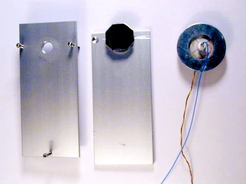
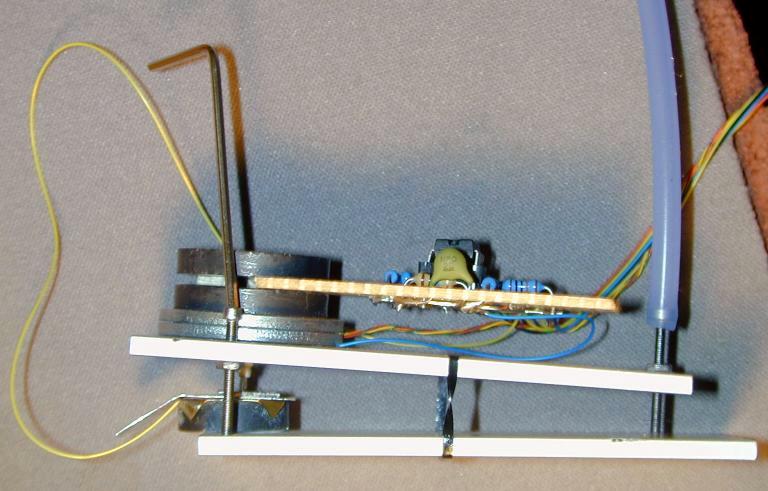
The disk scanner assembly is covered in detail, in subsequent pages. The remaining parts of the mechanical design are basically a sample stage, a scanner holder, and three screws that form the approach mechanism. The approach mechanism is basically a lever (sample stage) moved by three fine pitch screws. I cut two pieces of flat aluminum stock 1/8�x 1-�� by about 3-3/8�. One to hold the disk scanner and screws, the other to hold the sample.
Scanner Holder 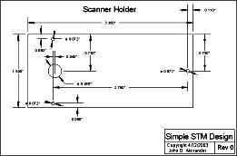 PDF image(inch) PDF
image(mm)
PDF image(inch) PDF
image(mm)
For the Scanner holder I
drilled Four holes in the aluminum stock piece (see diagram) . One hole
large enough for the scanner post to pass through with plenty of clearance
and three clearance holes for the UNCF #1-72 screws, see diagram. (Originally
I drilled and tapped the holes but the threads in this thin soft aluminum
did on hold the screw securely.) I super glued two 1-72 nuts on each hole,
one on each side. To insure the thread was aligned I put a screw through
the hole first and very lightly tightened the nuts on the screw before gluing
the nuts to the aluminum piece. If you over tighten the nuts you will not
be able to turn the screw when you�re done, and be careful to keep the glue
off the thread of the screw.
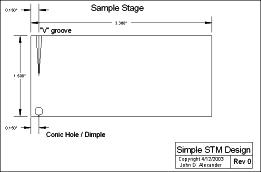
Sample Stage
 PDF image(inch) PDF
image(mm)
PDF image(inch) PDF
image(mm)
The other aluminum stock
piece is for the sample stage. I first marked the location of where the
three screws from the scanner mount touched the when the two pieces are
lined up with the screws extended. I made a ~ kinematic mount by using the
point of a large drill to make shallow a conic hole on one landing point
(see diagram) , and used a small file to make a �V� groove through another.
The screw landing point far from the tip should be a flat surface.
For this design I used a ceramic magnet disk to hold a removable sample
stub (steel disk or steel washer that the sample is glued onto with conductive
epoxy or paint) Ceramic magnets are usually fairly good insulators. To make
electrical contact to the sample stub I glued a very thin piece of brass
shim stock on top of the disk magnet and soldered a wire to the brass shim.
This wire was connected to the sample bias voltage. I glued the disc scanner
and sample holder onto their respective aluminum mountings (see diagram).
Mounting for the pre-amplifier
As a temporary mounting for the pre amplifier I placed a magnetic disk
on the back of the disc scanner, placed one edge of the pre amplifier circuit
board on top and set another disk magnet on top of the first. With the edge
of the pre-amp in between the magnets, this holds it like a clamp and the
pre-amp can still be removed easily. If you want to drill mounting holes
and put in standoffs and bolts that would be more professional.
Home Simple STM Project Home Project Overview Progress
Mechanical Design
Disk Scanner Description How to Make a Disk Scanner Mechanical Approach
Mechanism
Mechanical Bill of Materials Electronics Design Electronics Schematics
Electronics Bill of Materials Operating the STM Images
