Progress report 4/12/2003
I have added "Mechanical Design" and "Mechanical Approach Mechanism" pages. I wanted to get this section of the web site completed. Before I begin a new section on the $200 computer controlled STM, and a more user friendly web page frames layout. I am still answering questions when I have time.
Progress report 7/31/2001
I have had little time to work on this project other than answering a few questions. I have added some updates to this site, a description of the electronics, and a question and answer section.
Progress report 11/19/2000
I am Glad to report that an undergraduate student has build a working STM, based on this design. Marlini Pillay a student University of Natal (Durban) has reported imaging a gold surface and a grid with his microscope. A number of people have contacted me with questions. I will try to add more to the web site to answer the more common questions.
Progress report 5/5/2000
I have been busy with my new job but I am starting to get some more time now. I have modified the electronics to provide complementary drive signals to the +X and -X and +Y and -Y. I did this modification to increase the scan range but it also seems to reduce the background slope. I will post an updated schematic with the new XY driver soon.
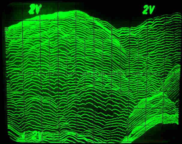
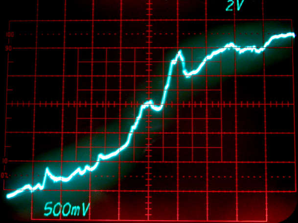
I used the old storage scope to record these line plots of Z+ Y vs. X. This is the gold coated diffraction grating again. Even with the larger scan range this 1mm grating is still too large. I did check the grating with a laser pointer it is a 1mm 2D grating. My best estimate of the XY motion is 0.06mm/Volt.
Approximately 1.25 x 1.25mm Image
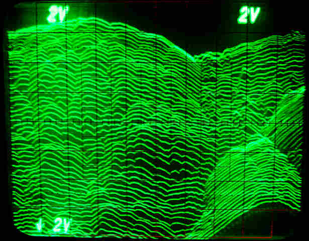
This image was taken about 4 minutes after the previous image
Progress report 2/9/2000
These are examples of line traces on a gold coated 1mm diffraction grating. I was hoping to be able to see one full bump. My first approximation suggested that the XY scan range would be about 1.5 mm with a 20 volt signal applied to the scanner. It looks like my guess was off it is at least half that range. I will try making an extension to the scanner so I can increase the range and calibrate this scanner against this grating. You can see from this line traces that the servo is tracking and the scans are repeatable. The line scan rate was about 3 Hz. These images were taken about 10 seconds apart. I have directly measured the motion of similar disks at 0.16 mm / Volt, so the vertical scale on these images should be 0.08 mm / division.
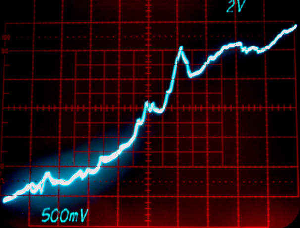
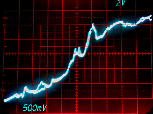
Notice forward and backward traces don't always overlap.
Progress report 2/6/2000
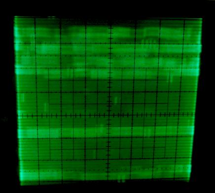
This is an example of a bad image. I just fixed some minor problems in the electronics so I hope to get some good images soon.
My pre amp intermittently went into oscillation. It seems the op-amp did not like driving the cable back to the control electronics I added a 220 Ohm resister before the cable to fix the problem. This is not unusual but not expected for such a short cable. I also increased the time constant of the integrator by changing capacitor C4 from 0.1mF, to 1mF. This gives a larger usable gain range. If the gain is too high the servo will oscillate. Previously there was only a small range of adjustment that the servo was stable. See the revision B schematic in the electronics section. I also added some very preliminary operating notes, and a mechanical bill of materials.
The microscope does servo to track the surface you can see the Z voltage change as the fine approach screw is turned. I think I just need to try a few more times now.
Home Simple STM Project Home Project Overview Progress Mechanical Design
Disk Scanner Description How to Make a Disk Scanner Mechanical Approach
Mechanism
Mechanical Bill of Materials Electronics Design Electronics Schematics
Electronics Bill of Materials Operating the STM Images
